Saturday, May 21, 2011
Tales From The Technical Fringe: Building A Tube Matcher
This is a little off the subject of Judybox amps but it may prove useful. I'm a semi pro amp repairman in addition to my other hustles, and I've had 4 or 5 Ampeg SVTs here for work mostly from one music shop. Anyone who's spent any time with the newer generation of SVTs knows a couple of things.
First, there's what I call the "Honey, I've got a headache" system. It consists of a couple of circuits that monitor bias current to the power tubes and allow you to adjust it within a certain range. If the system detects a fault in the power tubes, it throws the amp off line and it can't be gotten out of standby until the fault-perceived or otherwise-is rectified.
The general consensus is "Put in a matched set of power tubes-it may fix the problem, it may not." Of course, for a sextet of 6550s or KT88s, you're going to drop a minimum of $160 for the privilege of finding out whether you're right or wrong-maybe.
Why maybe? Because there are four separate integrated circuits in the system, a thermistor and a couple of relays, too-any one of which can produce faults in the system-not to mention the 220 ohm screen resistors on the tube circuit board. In such instances a set of tubes will only do damage to your billfold.
And thereby hangs a tale.
There is no longer such a thing as a good reliable 6550 tube in existence. Of the four makers in existence-Reflektor, Svetlana, JJ, and Shuguang-none are close to the reliability and ruggedness of the old GE or Tung Sol products. Couple that with the SVT's penchant for running the tubes damned hard, and you have a recipe for regular problems. I realized a while ago that if I was going to do any work on SVTs I had to have a good way of evaluating and classing power tubes.
Thus the Jack Price tube matcher, for which a schematic, layout and bill of materials can be found at the old Priceless Amp Restoration website.
A tube matcher's a handy thing to have, but just like Jack I found that the commercial items like the Maxi matcher were awful pricey. The Maxi matcher also tests at only two voltages, 325v and 400v. That's not nearly enough when today's guitar and bass amps are pushing hard-the SVT slams the power tubes with about 660v.
I figured I had the parts to build it, so I started on it a couple months ago.
My tube matcher is based on the Jack Price schematic but with several differences. The chassis was from a Bogen PA amp I had. I sold the transformers out of it and netted $25 so I was ahead before I started.
The filament transformer was donated from an organ that was running about 40 12AU7s so it has ample capacity. It runs at about 6.7 v unloaded and with 3 6550s and an EL34 powered up it only drops to about 6.4v. There's a 330 volt center tapped winding as well but I figure that was a power supply for a field coil speaker.
The power transformer came from an auction I went to in Ames, Iowa some years ago. There was an old split window Dodge van back behind the mobile radio shop that was closing and it was full of Thordarson stuff and rodent droppings. I bought a pickup load of the heavy stuff for a Franklin and this was in it. It's a Thordarson 26R35 television power transformer which is rated at 275 ma plate current and has 400v on either leg. The B+ ended up being 550v at 120v, and with the variac I can up that some.
Because the Thordarson transformer had no bias winding I had to set it up a la Marshall JTM45 off one side of the high voltage winding. It required a little tinkering to get the resistances right but I can now get anywhere from 7 to 100v negative. It's got about half a dozen 5V and 6v windings that I didn't use except for one for the pilot light.
I had most of the other parts in house-tube sockets, hardware, pop rivets, spray paint, and the only thing I bought was a big bag of terminal strips from some guy on ebay.
I had a 3 amp variac in the garage that I used to power the power transformer-it's a good way of adjusting the B+ to where you like it, bringing it up carefully as you go. I start down at about 300v and ramp it up slowly while monitoring the bias current on one tube for excursions and alarms.
I went to test it last night and promptly blew all four fuses. What I'd forgotten was that bias voltage is inversely proportional to bias current, and when I thought I was turning it down it was going up. POW!
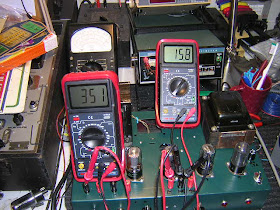
After reviewing my buildup and checking everything I tried it again, new .5 a fuses, with the bias control in mid span and it worked fine. I've got four 6V6s on test at about 350v in the picture. I chose not to use the 4 position selector as it was easy enough to bring the test points out to binding posts. I also tested a set of TAD 6L6GCs that were alleged to be matched-and they are, within 2 or 3 ma at 450v.
This is a relatively easy project to build even if you buy the transformers and a chassis enclosure commercially. If you tinker with amps at all it is well worth the effort.
UPDATE: After I completed this project I started evaluating a pair of 6550s and a pair of KT88s that I borrowed from a friend. Things were fine up to a certain point and then my multimeters would all get hysterical and I'd have to dump the voltage. I turned on an AM radio in the shop and it was clear that what was happening was oscillation. Dave Bane of DB Electronics suggested I incorporate some plate load resistors, which I did, and I also added a few snubbers here and there. It's all good and works fine. I've revised the Price schematic which is attached.
Saturday, May 14, 2011
Judybox Photos
I've been trolling the web for images and I've come up with some finds. The first series from top to bottom is an unnamed head that's for sale on ebay presently and the second series is some photos of a Judybox Thumper in the build stages.
The lead dress looks a lot different from first to second which leads me to think that the ebay amp has been hacked pretty severely.
Also, there's a photo of Revival serial number 202, which means there were at least 20 or so made as the Redhead is serial number 221 and the sticker for serial number 203 was lying around loose in the back of the Redhead.
Wednesday, May 11, 2011
Vintage Parts Excursion Crashes and Burns
I went to an auction Saturday and bought four cabinets full of vintage capacitors-Mallory Gems and Sprague Black Beauties, so I thought it would be nice to outfit the Redhead with a suite of cool old vintage capacitors and see how it sounded.
Well. It barely worked at all. No volume until about half way up and then it let out a strangled squawk-or maybe it was a burp.
I removed the chassis from Brownie and laid them out side by side on the workbench and proceeded to retrofit the Redhead with exactly the same values in the same places, adding and removing nice new parts-yellow polys as required.
In doing so I also took the opportunity to validate my board layout and bring the Redhead back to Brownie configuration. At that point I also found that what voiced the second channel in the original Redhead configuration was a 150k resistor in series with the first grid on the second preamp tube, and a small silver mica capacitor bridging the channels. Both items were noted and removed. One .1 uf capacitor was added in the same place it exists on Brownie.
The result? It sounds just like Brownie, only a little heftier because of the bigger output iron.
The Bad Betty speaker sounds pretty good as well.
So the board layout is complete, noted and checked for accuracy, and I can now concentrate on the connections to the tubes and controls. At that point I can proceed to start a schematic.
I guess what I learned is to check stuff carefully before installation, especially if it's old stock.
Tuesday, May 10, 2011
Custom Guitar Gear
Friday, May 6, 2011
Crates Are Good For Something After All
The Judybox output transformer on the Redhead was acting a little strange, so I decided to change it out. What was happening was in measuring plate voltage one side was OK but the other would make my multimeter go crazy and drop off line. It also made a lot of audio noise at the same time.
After looking around the place and interviewing several likely prospects I settled on the output transformer from a Crate TV6212 amp that I bought for some reason that escapes me, and that has become something of a parts bank.
You can see from the picture that it's got a bit more metal than the unmarked Judybox iron alongside of it, and it is an American made as well, from before SLM got bought out and the new owners got the yen for Viet Nam and other mesne places. Once the extra holes were drilled and it was secure and wired up, the voltages started acting normal again.
It's about the same piece of iron as a Bassman output, so I'm calling this a stage II mod-upgrading the output iron.
Tuesday, May 3, 2011
Transitional Year Website Shots
More Screenshots From The Judybox Site
Here are the last three iterations of the Judybox website I found-prior to the announcement of the Revival project in 2006, dating from 2004, 2003 and 2002.
It seems that at this point the company was still something of a one-off, craft industry, custom building house.
The transition page is interesting even though the pictures are down.
Enjoy. I think I may start trolling the web for interesting discussion threads and other items.
It seems that at this point the company was still something of a one-off, craft industry, custom building house.
The transition page is interesting even though the pictures are down.
Enjoy. I think I may start trolling the web for interesting discussion threads and other items.
Judybox Website Archive
Redhead Power Supply
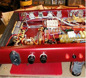
Here's a look at the Redhead with the Stage 1 power supply mods completed, the tube sockets replaced, the diode protection mod on the rectifier tube and the Fender style pilot light assembly installed.
I've yet to remediate the grounding scheme and replace the power receptacle.
I did remove a number of slabs of ....hard to describe-aluminum foil backed with very sticky, thick rubbery asphalt that had been attached to the inside of the chassis. There is some other schmutz in the corners of the chassis that has to go. Interestingly this amp came from Corpus Christi, Texas and its life in a shore environment showed up in the surface corrosion I found.
I've noticed that the output transformer is a bit odd-one side shows vP as it should but the other side is lower by about 15 volts and it makes my multimeter go crazy at the same time. I do have a nice old Thordarson 25w output transformer that I may swap into place for fun, or maybe I'll shop around for something interesting-I do have a nifty 30w transformer from an organ....but if the idea is to develop a series of product improvement mods maybe I'd better stick to commercial items.
I've also noticed that there are some differences between Brownie and the Redhead on the circuit board component choices. As the goal is to make the Redhead sound like Brownie, I'm likely to bring this amp back to that build standard. At this point I've nearly completed a circuit board map.