Monday, December 19, 2011
Repurposing A Courtesy Outlet
When installing a grounded three prong power cord on a Fender amplifier the question always arises "What in heck am I going to do with the courtesy outlet, which is itself ungrounded?"
It occurred to me a while ago that the courtesy outlet occupies the same footprint that a garden variety octal socket does. As I was in the process of replacing the two conductor cord on an AC568 Bassman, I also found that the power tube sockets needed replacement. It was a good opportunity to remove the hybrid cathode bias setup that Fender briefly used, and convert the bias balance to a simple bias level adjust system.
The only reason I can see that the hybrid system was used would be to ensure that if you lost your bias supply the amp wouldn't go into power tube melt down mode. It didn't last at Fender.
Checking the bias on a Bassman or similar amp configured as a head is impossible without removing the chassis, which can be problematic if changing tubes on the fly or between sets at a gig.
I took a replacement socket and installed two 1 0hm 1w 5 per cent resistors as shown. I wired each to the cathodes of the power tubes, and downstream I grounded the cathodes.
Now, setting the multimeter to millivolts will give cathode current in milliamps, and this can be read while the chassis is still installed in the head cabinet. In addition, each individual power tube cathode current can be read. Knowing the plate voltage allows the operator a safe range in which to operate, or alternatively to choose a spare set of power tubes for the road bag before leaving home.
You could bring out plate voltage to one contact but that could be a little hazardous with the number of little kids with sticky fingers that seem to always be underfoot. Better to leave it inside where it's safe.
In case you were wondering those screen resistors are Dale 2w metal film from Mouser Electronics. They meet the need and occupy a lot less real estate.
New Arrivals and A Project
A couple of new amps arrived here at mi ranchito for stays of indeterminate duration. One's a silver face Deluxe Reverb with the volume boost about which little need be said except that nobody ever uses the volume boost. It needs a little love in the form of a cleanup and a new vibrato roach which will be ordered this morning.
It remains to be seen whether I'll form a bond with it, although the Dragon Lady said "Oh. You can keep that if you like." Which was a big surprise, and it raises questions about whether I've got some kinda Stockholm Syndrome thing going on here but whatever-I'll take de job.
The second is far more interesting but enigmatic, and when I heard it had a 15 inch speaker I was hooked.
It's the Maestro M216 RVT pictured at left, and it's some sort of weirdo production from the Gibson works back in 1963 which was when it was made. The tube lineup is 5Y3-6V6-6V6-6EU7-6C4-6EU7-6EU7.
I've acquired it in a trade for a home brew consisting of a Motorola HS621 chassis mounted in an old Masco speaker cabinet with a 70w Eminence topping it off. It sounds surprisingly good and it appealed to the previous owner of the Maestro. The deal's done, and all that is needed to seal the deal is for me to hand over a couple of Franklins.
The circuit is unique and resembles only the GA19RVT Falcon in the Gibson Master Service Manual, but it is voiced differently-allegedly for accordion. It's single channel with swampy reverb and vibrato, but the amp just doesn't have enough volume. I spent most of Sunday afternoon trying different things to see if I could raise the volume level to acceptable levels-changing resistance values in strategic locations, installing a larger output transformer from a Deluxe Reverb, a solid state rectifier module and bypassing certain components to see whether the mystery could be unraveled.
All was in vain-even though I did find a resting place for one of my 1957 vintage Jensen P15R speakers. A general cleanup and chrome polish was had, and I subbed some Dakaware stove knobs because I just don't like those red pointers any. The knobs came from a tube tester I scrapped a while ago.
So, it seems I must study circuit design and topography to unravel this mystery. One clue that I have uncovered is that if the volume control is dimed, there is next to no white noise-which tells me something's rotten in Denmark.
Friday, December 2, 2011
Resuscitating A Silvertone 1396 Twin Twelve
I'm a sucker for projects, so when a friend brought me a Silvertone 1396 combo that had been in a barn for twenty years or so after being stripped of its speakers and grillcloth I was on board.
The owner represented that it had worked at that time but I find that belief problematic. There was no discernible preamp action, which I later discovered was because the cathode resistor upon which all in the preamp department depends had gone open. It fell apart in my hands, actually.
A preliminary power up with some borrowed speakers showed that the audio section and power supply was functional although needing a complete suite of new tubes and a thorough going over.
Down below there are two separate output transformers, each of which feeds its own speaker. It thus satisfies the Daniel penchant for weirdness and complexity coupled with cheapness of build. But nevermind.
Not so the top chassis-and thereby hangs a tale.
The top chassis contains the controls, a smallish phenolic slab that mounts eight capacitors, four resistors, a tube socket, and a single 12AX7 tube.
Looking at the schematic you can see that the filaments are in series with the cathodes of the power tubes-a favorite Nat Daniel Red Bank era feature.
The upper chassis is a nice cozy place, and it looks as if a field mouse or two shacked up in there for a while, using the upper chassis as a latrine and a source for things to gnaw.
Another feature of this amp is the blue green Sangamo capacitors, all of which showed unacceptable leakage and got tossed. I didn't even need to fire up the capacitor tester I built a while ago, as my trusty IRT2 insulation tester showed enough leakage to make that irrelevant.
The upper board required a complete stripout of all the components, a thorough cleaning and a rebuild that included a new shielded Belton tube socket.
After a few fits and starts and a bit of rework, it's as good as it will ever be. The speaker chores are being taken care of by a pair of period vintage Quam Nichols alnico speakers that came out of a PA enclosure I forgot I owned. They looked almost new, and I doped the somewhat light duty cones for good measure.
Finishing up the upper chassis I bridged the channels for more volume.
How's it sound? Bright and articulate, but the vibrato is slow and dreamy and it will take you to Link Wray "Rumble" territory in a short time.
It's not as in your face as the current day run of cheap amps, but it definitely is one to put on Santa's list. They're not the most common amps in the world either, mostly because they weren't built to last fifty years as this one has.
Friday, November 25, 2011
Son of Judybox Mark II
I completed the second Son of Judybox, a/k/a Vamp tonight and at this point it is an unqualified success and ready for prime time.
If you've been following this saga you know that I was able to find a way to reuse the original Chinese made Ningbo Chaobo power and output transformers that the Champion 600 is equipped with to make this project a lot more affordable-at least $68.00 or so, depending on where you shop.
The problem was that the original power transformer had no 5v rectifier tube winding and the secondaries have no center tap. This was solved with a modified Graetz bridge and a 6X5 rectifier tube as indicated in the Yes You Can posting a few weeks ago, and a good solid 330v of DC and 6.4 filament volts was obtained with everything up and running. You could probably use a 6X4 as many Silvertones did, but it is a lot easier to wire up an octal socket-there's more room to work-and you have an octal socket sized hole ready made for the purpose already where you want it.
The schematics for this setup have been posted here, and the only change would be to add a pair of 100 ohm resistors, one on each leg of the filaments for noise reduction as the original power transformer filament winding is without a center tap either. I wired the filaments with two wires, where the original 5C1 uses the chassis for one side of the filament string.
Another useful thing to remember is to use a grounding jack for the input for noise reduction.
To summarize, then. The original speaker jack was removed and a fuse holder was installed after opening up the hole. Two holes were punched in the chassis to accommodate the two additional octal sockets. Care has to be taken to avoid interference between the 6V6 in the center and the speaker basket or magnet.
A piece of perf board did service for mounting the electrolytics and dropping resistors, and the rest of the components were wired point to point. The lead from the jacks to the preamp tube is very sensitive to interference, so I shielded it with about thirty turns of hookup wire wrapped around a pencil and slipped it over the lead and its capacitor.
At the same time I installed a 1 meg audio pot for the volume, a standard Fender pilot light assembly, and reused the original power switch, saving an extra three bucks there.
The last bit of the puzzle was getting the sound right. I first tried a Weber 6x9 inch ceramic speaker but it didn't get the job done.
Luckily as I was up in Minnesota hunting in a dead TV repair shop last week I uncovered a nice 1957 vintage 6" Rola radio speaker and that does the job just right.
Another good idea is to remove some of the aluminum tape shielding in the cabinet above where the fuse holder sits-otherwise you can get a few sparks if the amp is jounced pretty hard.
You can have tube rectification with all the sag and touch sensitivity that conveys and still retain the original iron which seems well up to the task. You save enough dough that you can go out and get yourself a big hefty output transformer and still have thirty bucks to buy some beers.
Saturday, November 12, 2011
Fixing a Dead Standby Switch on a YCV40
A Traynor YCV40 arrived recently with a failed standby switch and it presented an interesting problem. Seems the switch actually controls a FET (field effect transistor) that controls the B+ voltage, and a shorted power tube will kill the FET.
The fix according to Yorkville was to replace the FET (Q8) a small 10v zener diode (D13) and an integrated circuit (U3). U3 is the little white square in the picture, Q8 is the transistor on the right and D13 is too small to see easily but if you start at U3 and count to the right it's the sixth device, to the right of five resistors. Make sure you check the part numbers on the FET and the IC because in this case the amp I was working on used a different device-note it has only six legs. Make sure you use some fresh heat sink compound under the FET.
Q8 is an IRF 830 FET and U3 is a 4M35 integrated circuit. Don't quite remember the part number on the zener but it's in Traynor's excellent service manual.
Also these amps were built with lead free solder so be prepared.
Thursday, October 13, 2011
Champion 600 modified schematic Mark II
Here's the complete schematic for the low cost 5C1 retrofit using a donor Champion 600 and retaining the original equipment transformers. If you're building this make sure you position the 6V6 so as to have adequate clearance between the tube and the speaker basket.
ERRATA: I got the diode numbers screwed up here so just go ahead and substitute the omnipresent 1N4007 and double them up for safety's sake.
Monday, October 10, 2011
Yes, You Can and the Champion 600
Part of the Mark II Champion 600 to 5C1 modification program was intended to lower the price of the modifications substantially by reusing the original Ningbo Chaobo power and output transformers.
That presented a smallish problem because the power transformer was without a center tap or the more typical 5v rectifier winding.
The first objective was to wire up the filament circuit and see if the 6v filament winding had enough stamina to survive. This was done by comparing the unloaded and loaded voltages. Unloaded the winding produced 6.7 volts ac. Installing three tubes-a 6X5, a 6V6GT, and a 6SJ7-and powering up produced a voltage drop of only .3 volts, and it stabilized at 6.4v which was serviceable.
The second objective was to see if there was a way to use the transformer with the rectifier tube. A bit of looking around and chatting to people led me to a drawing of a hybrid power supply on diyAudio drawn by A. Ciuffoli, which is sometimes called a hybrid Graetz bridge.
It consists of tying the plates of the rectifier tube to ground by means of the diodes shown. I used the 1N5408 which is a bit heavier duty than the omnipresent 1N4007 diode, and then I doubled them up for good measure. Connecting pin 8 of the 6X5 tube to the load produced a good solid 360v of DC right where it is needed.
With all tubes installed and a load connected, I'm getting 330v-316v-273v on the B+ rail which is plenty for this job. By comparison, the original solid state rectifier setup in this amp produced 360v according to my notes, which puts this right on the money. According to the Sylvania technical manual, the voltage drop for this tube should be about 22v, which means I'm close enough for guv'mint work.
So. The proof of concept is good, much money will be saved, and you heard it here first.
Thanks to Mr. Ciuffoli, wherever he is, and the folks over at diyAudio who think hard about such matters.
ERRATA: I got the diode numbers screwed up here and on the schematic so just to be on the safe side use the omnipresent 1N4007 for the legs from the HV to ground and double them up as I did.
Thursday, October 6, 2011
Second Son of Judybox Project Underway
As part of the retro mod Son of Judybox project I acquired for a Franklin an allegedly defunct Champion 600 that arrived this afternoon from beautiful downtown Cody, Wyoming. As it happened this was because the preamp tube had come adrift. Once reinstalled it was fine.
After some fits and starts the first Son of Judybox project turned out to be a good exercise in repurposing, but the objective here is a little different.
I want to try and reuse the Ningbo Chaobo (I ain't kiddin') transformers and compare the sound to the fully retrofitted 600, because if I can, I can lower the price of this modification substantially. The original power transformer does not have a 5v rectifier winding, but if it can stand an additional 600ma of heater load I figure a 6X5 rectifier tube will do swimmingly. I could use a 6X4 but with my fingers I need octal territory to work in.
So the objective here will be to measure the original filament voltage with no tubes and then with tubes to establish a baseline voltage and then install the filament string to measure the draw and test the power transformer temperature. The original load, according to the Sylvania manual, should be about .75 amps and the design load adds up to 1.35 amps, the difference being the .6 amps that the 6X5 draws.
The other idea I have is to use one of Ted Weber's 6x9" oval speakers he engineered for the Valco crowd.
Stay tuned.
Wednesday, September 14, 2011
Tube Matcher and Magic Wand Update
Ever since I built the Jack Price Tube Matcher I've been thinking a precision adjustable feature might be very handy to have when calibration time rolls around or there's a need for more precision.
After some thought and research here is what I came up with.
It requires eight 10 ohm precision trim pots, which are the lowest resistance value commonly available. The specifications say that these have no more than 2 ohms residual resistance, so I figured that doubling them up would get me right in the range needed as well as doubling the wattage rating. I mounted the pots on a piece of perf board and I'm going to try it out soon.
I think that setting up the tester with a single tube and then adjusting each socket to read exactly the same on the multimeter will fulfill the calibration function, and this could also allow compensation for any drift in the other parts of the system.
I also added a picture of a neat little signal tracerish idea from the Hoffman Amps website. The idea is to take a small audio amplifier set up for clean sound-in my case a $25 Crate bass amp off of Craigslist. Then taking a multimeter probe and connecting it with shielded wire (old guitar cable) to a project box containing a 1 meg pot for padding and a .1/600v cap for DC blocking completes the gizmo.
Now, you set up the amp under test to your dummy load about which more anon. You have some compliant soul play a guitar through it and using your newly built signal tracer you follow the signal through the amp until it deteriorates, thus locating the source of your unwanted distortion.
Monday, August 22, 2011
Further Tales From The Tonal Fringe: The Ampeg That Nearly Wasn't
A couple of weeks ago I had gotten an Ampeg jones and started trolling Craigslist for likely suspects. I found an ad that had just been posted from the Lincoln, Nebraska area and it was for a 1961 Ampeg M-12-the very amp you see in the pictures, and thereby hangs a tale.
I talked to the owner on the phone and I had his first name, phone number, and a place to meet in his smallish town north of Lincoln. So the Dragon Lady and me climbed into the Honda a/k/a Jackie Chan and headed west.
About 200 miles later we were there. I dialed the phone number I had been given and it was the fellow's work number, an answering service and they were completely unhelpful, didn't know anything and couldn't do anything until Monday. I then went through the Valparaiso phone book and called every Kevin in the book. No joy. I found the local public library and convinced the librarian to post a response to the ad which was still up on Craigslist, and went back to the meeting place.
Just as I was settling in for a good wait, I saw a red Dodge truck hurtling down a side road and it was our guy. His wife had intercepted the message and called him.
The amp was secured, cash was paid out, and I and the Dragon Lady retired to Lincoln for a repast at Five Guys.
How's it sound? It's clean, with a swampy vibrato, and cosmetically it is a peach. It is the early style 'random flair' vinyl covering with silver sparkles that predates the more common herringbone style covering. It sounds so good I'm seriously thinking about selling a couple of other amps I have here.
Monday, August 1, 2011
Vintage Parts Excursion Part IV: Son of Judybox Champion 600?
A friend of mine dropped off an early fifties Fender 5C1 Champ for an overhaul and it sounded so good I decided to make my own. Looking around the shop I found my Champion 600 reissue that has been lounging around with the occasional task of testing preamp tubes for excessive noise. I also gathered up a trio of tube sockets, some capacitors, a bit of perf board that had been used as a bookmark, and the main ingredients-a Stancor new old stock power transformer and a Thordarson output transformer, both of which had come out of the split window Dodge van. It took a few hours to gut the Champion 600 innards and repurpose it.
The first thing I did was ditch the speaker out jack and bore the hole out for a fuse holder. At that time I also installed a SPST power switch and, using a Greenlee type punch from Harbor Freight, installed a trio of tube sockets. Then a trio of 22 uf capacitors and suitable resistors completed the power supply setup. A test confirmed proper voltages at all the important places. Then, I wired up the 6V6 power tube and the 6SJ7 preamp tube.
It sounds remarkably like the old 5C1, but the speaker's a little more hi fi, so I'm looking for a nice period Cletron or similar fine speaker. The combination of the 6SJ7 pentode and grid leak bias is the tonal ticket. It'll slide right into a nice greasy blues tone, and with the right pickups it's a joy.
You could probably re-use the Chinese iron if you wanted to use a 6AX5 rectifier and reutilize the output transformer. But you might miss out on the magic.
To reproduce this project for you, it would cost you about $120 in parts and shipping for Magnetic Components iron, shipping both ways, and about $120 in labor. Tubes would be about $24 extra for a NOS rectifier and preamp tube and a vintage serviceable 6V6. If you like the idea, drop me a line.
UPDATE:
I did have a few issues with this circuit that it is worth knowing about. The lead between the 2-75k ohm resistors and the preamp tube is very sensitive to positioning and has a bad tendency to create oscillation.
After a few fits and starts and some blind alleys I ended up taking some hookup wire and wrapping about thirty turns around a pencil. I then stuck the lead through this coil and grounded one end. The Jensen Mod came in at about the same time so that got installed, offset a bit for clearance. The result's a lot cleaner and the volume can be maxed with no oscillation or interference. I'm still looking for an older 6" speaker-that'll really do the job of recreating a classic.
Wednesday, July 27, 2011
Brownie Hits The Road
Brownie traveled with me to New Jersey last week and impressed the locals with his verve and can-do attitude.
Tuesday, July 19, 2011
Vintage Parts Excursion Part III: Building A Usable Capacitor Checker
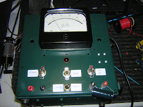
After a few fits and starts and trips along a few blind alleys I managed to get the capacitor checker project up and running, and it's a pretty nifty piece of gear. This device will test capacitors for leakage in microamps and also can be used to reform electrolytics and check them for leakage. It has three ranges-10 ua, 1 ma and 10 ma. The meter movement is a 199 us Soviet military surplus job, and the cabinet's prior tenant was a Jackson 645 VTVM.
In the picture you can see a new old stock Mallory capacitor leaking about 80 ua of current and an orange drop Sprague showing about 1 ua of leakage, both at 350v. Also there's an electrolytic on the 10 ma range showing about 2 ma of leakage and it settled down after a while.
I've included two different schematics for devices of this kind.
Thursday, July 7, 2011
Tube matcher calibration
One of the problems with any kind test equipment is doing some real world calibration and I tried a number of different ways of doing this with my recently constructed somewhat modified Jack Price tube matcher.
Ultimately what I figured out was to take a trio of tubes-6V6, 6L6GC, and 6550. Warm them up until they're stable, say, fifteen or twenty minutes or until the current gets as stable as it's ever going to be, and then get out your leather gloves and switch them to each socket in turn without touching the control settings. I figured that anything under 0.5 ma spread was all good and so it was.
These are now carefully stashed reference tubes, and I'm sitting on my string of 1 ohm resistors from the same batch.
One thing that did occur to me was to figure out a way to incorporate a trimmer into each tube cathode circuit for really tight calibration.
Film at 11.
Saturday, July 2, 2011
Vintage Parts Excursion, Part 2: Capacitor leakage tester
Since my last episode with capacitor leakage it seemed necessary to cook up another piece of guitar amp specific test gear to complement the tube matcher I built recently, namely, a direct reading capacitor leakage meter and reforming device.
The original schematic was something I found In Alan Douglas' Classic Tube Testers and Test Equipment, but I've modified it a bit to suit local conditions, as it were.
It started out life as a Jackson model 645 vacuum tube voltmeter that had been lurking in the dark under my workbench. I didn't have a need for it but I couldn't bring myself to part with it-mostly because I like Jackson test equipment.
I'd been thinking about keeping it as is but it needed a special purpose 4.5 volt battery I did not have, so I proceeded to repurpose it. I built the power supply out of a Hammond organ power transformer and more terminal strips. They're great for prototyping things as they can be easily pop riveted in a convenient place.
At present it's been mocked up and I'm trolling through my resistor museum for combinations that meet the schematic value. And that's one good thing you can do with a lot of old carbon composition resistors is find ones that you can use.
In the meantime I ordered up a Russian military surplus analog 100 microamp meter that looks like reverse engineered Weston stuff-a fitting tribute to the men and women of Frelinghuysen Avenue.
I'll probably finish most of the wiring this weekend of the Glorious Fourth, and then station myself by the mailbox for the package from Estonia carrying my spiffy new Soviet microammeter.
Stay tuned.
Tuesday, June 28, 2011
The end of an empire-maybe.
Through the acquaintance of a nice person in Austin I was able to acquire six more or less complete Judybox Revival (or they could be Hooligan) component tag boards, pretty much fully loaded. One's got a little damage but is repairable. Also part of the deal was a new power transformer and a fair amount of bagged components.
These came from when Judybox shut down for good, and the person who originally had these was a worker at Judybox.
There may be more, including some technical information which I would dearly like to get my hands on. It is said that in a garage in Austin awaits more goodies and the file folder with the technical stuff. Although it can be reverse engineered it's much easier to have documentation to work with.
Chances are I will rework these circuit boards to Stage One standard and then see what can be done with them.