Friday, May 17, 2013

Peavey 6505+ Biasing

A Peavey 6505+ arrived here needing a general going over. It was first determined that the power tubes needed replacing as there was a cathode current spread of about 17 ma, lowest to highest. I also tested the allegedly new preamp tubes and found one to be very weak.

Once I got my preliminary work done I powered the amp up on the bench and noticed it was very low on volume, and that there was a lot of crackling and popping when tapping the very flimsy preamp tube board.

Some cleaning and swapping was in order, but what cured the issue was replacing V5 with a new old stock GE preamp tube.

Setting the bias is relatively easy on this amp because there is an external control, but the range was sufficient to only get me to 17 ma-not enough by a landslide.

The fix is removing the 12k 1/4 w resistor on the bias control board and replacing it with a 6.8k resistor. Here you see the results with plate voltage at 439 and cathode current at about 35ma.

Although super high gain amps are not my cup of tea, this one seems to be reasonably well constructed for the genre, but the preamp tube board is a definite weak point. When installing preamp tubes from the outside the board can be felt flexing and viewed from underneath there's no doubt that this is not a good feature-there is not nearly enough support. In the attached pix you can see the back side of the preamp tube board, the bias control board that the range resistor gets changed on, V5 which was the source of all that trouble, and the finished result.

.


When doing my research I found that a lot of people on the chat boards treat the bias control pot as something of a dial-a-torque sort of arrangement. Turn the knob, get the tone-that sort of thing. I attached a warning label and taped over the control.


Friday, May 3, 2013

Bandmaster Build refried.

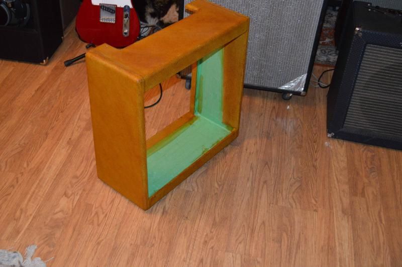
Here's a pic of how the cabinet turned out. I'm not real happy with it but I think a bottle ring and a few cigarette burns might improve the general appearance.

Linky


Sunday, April 28, 2013

Bandmaster Build Part 4: Sorting Out The Cabinet


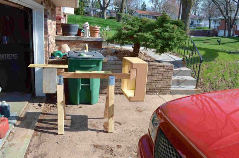
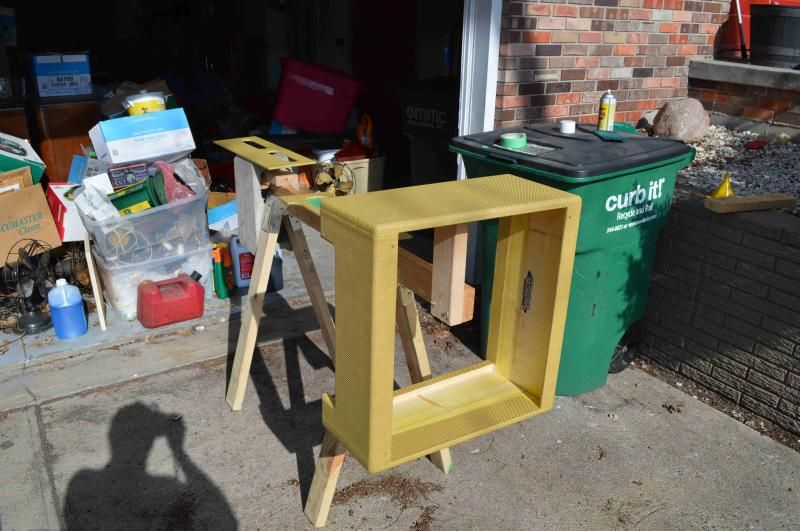
Once the weather warmed up enough to think about getting the cabinet shaped up for my 5E7 Bandmaster build I had to devote a little thought to making up a fixture for finishing the cabinet. I went out to the garage to see what could be found and settled on a pair of sawhorse leg connecters I'd purchased a while ago for the workbench project. A few chunks of 2x4 and some self tapping screws and I had it. Adding the extension made it easy to add a counterweight in the form of a cinder block that happened to be wandering by.

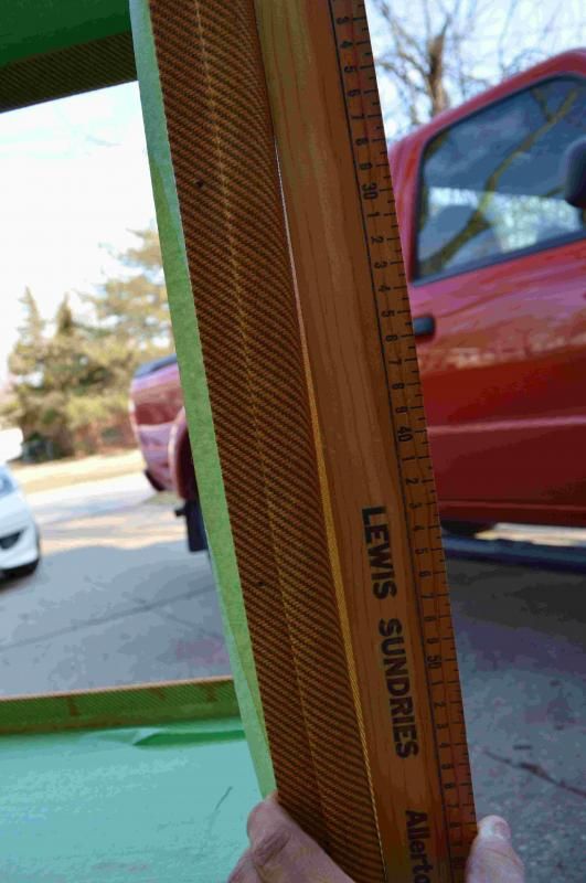
As I started putting the first coats of shellac on the cabinet-about which more anon-I discovered that the cabinet had been built with a seriously warped on one side board. I emailed the fine folks at Weber and they were good enough to provide another cabinet at no cost-props to them.

A few more weeks elapsed before the new cabinet arrived Friday last, but in the meantime I had had some time to think about the shellac finish and the prospects for getting a good application without discoloration-it is very easy for the end grain of the cloth to absorb the shellac which leads to permanent discoloration. It's liveable but I'm a perfectionist.

Some folks use Minwax Honey Pine polyurethane finish, but I don't like the look of the stuff at all-it's got a bit too much green in it and is far too slick for me, and I'm going for more of a tobacco coloration.

So I decided for my second try I was going to take my time and anoint the cabinet with clear shellac from the spray can, but that I was going to give it plenty of time to dry-like, a day or so, and pay special attention to the end grain of the fabric. Also, I decided I was going to build up the sealer coat substantially. So that's the plan and it's now baking in the sun after the second application.

I will probably give it another coat of clear and finish off the rattle can before I attempt to color it. I do have a can of clear shellac and I may try that as well. The object lesson is to take the time to build up a solid undercoat and properly seal the fiber. A light scuffing between coats after the shellac is properly dry is a must.

For those of you who haven't yet tried this, you need to assemble a spray can of Zinsser Bulls Eye clear shellac, a pint of their amber shellac, a quart of denatured alcohol, some green Scotchbrite scuff pads, a good brush, and some painter's tape. A fixture like I built can be thrown together in a few minutes.  All this can be found at any hardware store, so take the opportunity to shop locally and use environmentally friendly products from renewable and sustainable resources-which shellac and alcohol are, but which polyurethane most surely is not.

As a point of information, shellac is a refined naturally produced resin that primarily comes from India. The resin itself is produced by insects and it is deposited on twigs and small branches of host trees. You can read all about the production process here.

Although shellac dries to the touch in about thirty minutes, it's still not cured and that's where being in too much of a hurry can take a good job and turn it into an unsightly one.


Saturday, April 13, 2013

Bassman Hack


Here's an interesting Bassman a friend of mine recently acquired and sent over for service. According to the tube chart it is an AA864 but it's a hybrid between the AA864 and AB165 layouts. Well, nevermind.

What's interesting is the hack somebody laid on it. I guess the idea was to be able to run a tape player through it or something. I really do not think the guy knew what he was doing and it looked pretty nasty-not to mention he had the plate supply going through these pots whatever they were supposed to do. And a redplating power tube.  And some extra high quality soldering of the grounds. But nevermind.

It all came out easily enough, it got serviced and recapped, new power tubes and plate load resistors, and things were reassembled According To Leo. Some plastic plugs from the local hardware store were the best I could do with the drilled out holes on the back panel.


Friday, April 12, 2013

Gee, Ma, It Followed Me Home. Can I Keep It? The Excelsior Americana


Here's an interesting amp that followed me home the other day. It's an Excelsior Americana accordion amplifier, and it sports some unusual equipment-a 15 inch speaker, two 8 inch speakers, two tweeters, and a pair of EL34 power tubes.

It is rumored to have been made by the Sano people in New Jersey but I cannot confirm that. I was able to lay hands on a more or less complete set of schematics and they are reproduced here. It's pretty clean but needs a bit of work to get everything running properly-the vibrato does not work, the reverb just barely, and the controls are noisy as all getout.

Still, the guitar channel sounds a lot like a Fender of the era, with a fair amount of sparkle. And who knows, with the right accordionist you could stir up some real fun and polka.

Plus, it's weird and nobody else around here has one.

Friday, March 29, 2013

Bandmaster Build part 3

I finished the chassis a few days ago and road tested it on the bench while I was setting the bias. I lugged it upstairs and slapped it into my friend's 1955 Super cabinet that was vacant at the time and gave it a whirl. It sounds good, nice and quiet and clear tone. Metal film resistors are good for making a nice quiet running amp I think.

 I won't know how it really sounds until it's run through the three Weber alnico Signatures that were provided with the kit.

It was worth taking all the extra time to double check every connection on the board and each flying lead because I was not going to take the board out again.

Fact is, I'm trading a D'Evil for a Weber 5E3P Proluxe I used to own, and  I've already got a board half built and stuffed for a conversion to octal preamp tubes. Somewhere in this blog there's some information on how to make your own boards and drilling masks, and install and clinch eyelets.

Now, if the weather warms up a bit I have two tweed cabinets to shellac and tone.

Monday, March 25, 2013

Bandmaster part 2: Wiring The Backside Of The Board

Once I had the components dry mounted on the front of the board it was time to do the back side wiring. For the uninitiated this is the wiring that  is sandwiched between the insulation board and the back side of the component board, and there are more than a few wires. They've got to be installed and soldered to the eyelets unless you want to take it all apart again.

But what to do? The Mojotone manual has a picture of what it should look like more or less but I was not really satisfied with it. Then the solution came to me. The Weber layout diagram image was acquired on my computer and reversed so it showed the hatched lines for the back side wiring as if I was looking down on it from above.

Here you can see what I used to run the back side wiring.

Once the wiring was run I finished soldering up the components and the flying leads. At this point I did not know how long they'd have to be so all of them were 12 inches long. It required an order for some more Stewart Macdonald yellow waxed pushback wiring.

Taking the layout diagram and schematic I then made a map of every termination point on the assembled board and checked every lead for continuity and arrival at the proper destination. Some of the wiring came out from under the board but I moved it to the top for ease of maintenance should it ever need repair. Here's one fellow's assembled board which I used as a model.


And here's mine, installed in the chassis. It's not quite as pretty but taking the time to validate every connection for continuity and proper hookup paid dividends because  it worked as advertised when I powered it up. One thing i did not want were screwups that required a disassembly.

Once the board was in place all it required was stitching up the connections that I had tagged according to the map I made. As I had already wired up the controls and power supply previously, once I wired up the inputs and speaker jacks it fired right up.  With a 5R4 rectifier and a pair of 6L6GCs from the House of Ruby, I got a measured 430 plate volts and set the bias at 40 ma.

The next adventure will be when the weather gets warm enough to coat and seal the tweed covering and final install the chassis.