Wednesday, February 15, 2012

Bogus Bourns Pots on Ebay


While doing some searching on ebay, the "why pay more?" store, I found that quite a number of trimmer pots are not what they appear to be.

Here you have Borton, Baoshi, Bonens, Barons, Bochen, and Borans trimmers.

What you get is up to you, but the original product can be obtained from any number of reputable distributors for a relatively modest sum.
I sure didn't think it was worth gambling an amplifier worth several hundred dollars by trying to save a couple of bucks.

But that's me.


Tuesday, February 14, 2012

Converting an Ampeg V4 to adjustable bias part 2.


The postman arrived yesterday with a small package from Mouser Electronics that contained a few Bourns 3006Y 100k ohm trim pots of the multi turn, sealed variety.

As a point of information, avoid the bargain priced, what appear to be Bourns trim pots coming from Asia-a casual look at ebay reveals they're mostly fakes with lettering intended to look sort of like Bourns if you're not looking closely.

Bourns makes good sealed trimmers that should last indefinitely.

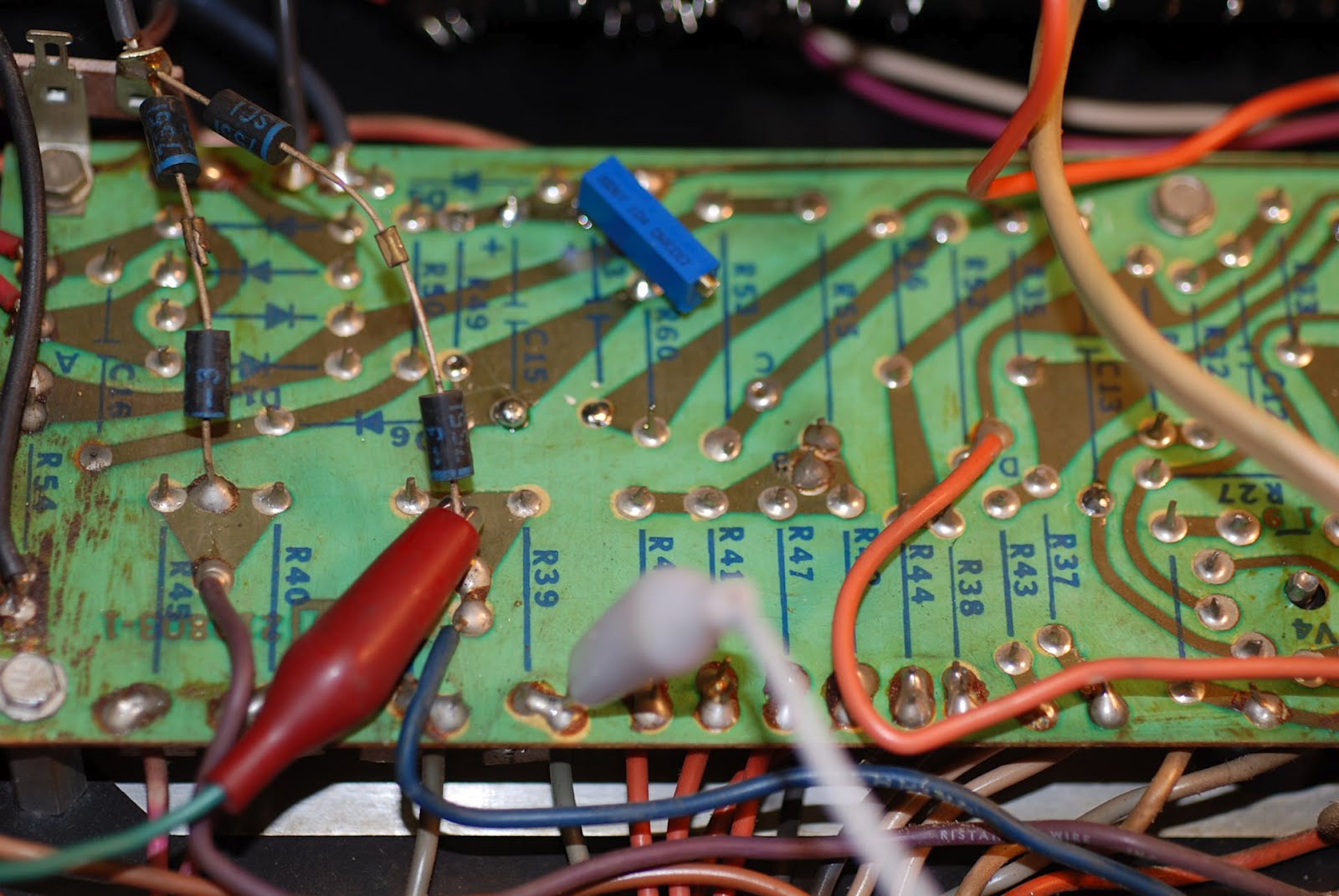
This pot is intended to replace R49 on the Ampeg schematic which is a 75k fixed resistor that sets the bias level.

The first thing I did was set the pot to about the same value as the resistor I removed. Then I started looking around for a good place to locate the trimmer. Looking on the underside of the circuit board I found a good place for it. I removed the third terminal and then, carefully heating the solder joints, pushed the wires from the Bourns trimmer in alongside the existing component leads.


You can also access the back sides of R40, 45, 46, and 39 which are the four plate resistors.

You should measure these for their actual value rather than their nominal value.

After a good warmup, I switched on and measured the VOLTAGE across R39 which read 73mv. Dividing 73 by the value of R39 which was 4.6 ohms gave me a plate current of 15 ma more or less, not enough at a plate voltage of 535v.

Carefully adjusting the pot upward I ended up at a final setting of 123.7 mv, which divided by 4.6 gives 26.9 ma of plate current. Adding in 4 ma of Kentucky windage to allow for screen current we're still well within what's allowable in this amp, with a margin for some upward drift as the tubes age.

While you're doing all this bear in mind you're working in close proximity to a live amp with some serious voltages. In addition, dropping things inside this live amp....well, the prospects are ugly. I made sure and insulated my trimmer screwdriver, although a plastic one would be even better. It goes without saying, easy does it and watch what you're doing.

Sunday, February 12, 2012

Service Review: The Blackstar HT40

This will be the first in a series of reviews of amps as they show up around here for repairs. I intend to look only at a limited number of parameters: ease of serviceability and availability of documentation. These opinions are my own


Recently a Blackstar HT40 like the one in the picture arrived. It had been arrested for attempted homicide, having tried to kill the owner with a jolt of electricity that actually melted a couple of guitar strings. It was bought used, so the warranty is not in existence.

The street price for these things is about $700 more or less at all the usual places. Cheap enough if you get good value but that's not what's happening here.

It looks like a nice stout production, but appearances can be deceiving.

During my preliminary information gathering process I learned that this amp has a processor on the circuit board that has some proprietary programming. That's the 32(?) pin number on the right with the sticker on it in the photo below. This processor with the special programming is made of unobtainium, kinda like the Maytag "Jazz" chip that caused my refrigerator to collapse and die. At least there I could get my hands on a schematic and a circuit board and it only cost eighty bucks.

You can read about that here.

In addition I found out that Blackstar service information is available only to authorized Korg service centers, which means it's not available to owners or to the independent service operators.

On opening up the amp for a look around I also noticed that the board is thin and flexible-and not in a good way, either, with circuit board mounted tube sockets already showing signs of distress and a wealth of surface mounted devices that are nearly impossible to remove and replace economically. For a 40w amp the output transformer is decidedly small.

I did find a burned trace on the circuit board and fixed it with a jumper and it now works intermittently when the jack is preloaded. Replace the jack? Didn't help.

One of the things we do when troubleshooting is to switch out suspect components as an information gathering and trouble localizing exercise-does this or that item change the parameters of the malfunction?

That's not going to happen with this amp because of the surface mount componentry. Between the lack of service information and the nonrepairability of this circuit board, most of these amps will end up in dumpsters or stuck in basements when they fail, which they all do inevitably.

How about the rest of it? Well, the cabinet is made out of MDF fiberboard-not the most damage tolerant product out there. Tonewise it is brittle and harsh sounding. In addition the solid state reverb is synthetic and cheesy sounding, like a cheap pedal from a junkshop.

I wouldn't recommend this amp to anyone. Amps always break sooner or later, and having one that can't be fixed economically is just a waste of hard earned money. Hell, even Crate will provide service information to owners and the trade.

Truth in advertising suggests that this should be called Crapstar.


Friday, February 10, 2012

Checking The Bias On An Ampeg V4B


Recently I have been overhauling an Ampeg V4B bass amp, and after all the necessary repairs had been made, the matter of checking the bias current raised itself. The bias probes I put together from Bruce Hoffman's parts do not, unfortunately, work very well with the owner's chosen 7027A power tubes. So....what to do?

After a little thought a solution suggested itself. There are four 5w cement resistors marked as PR1 on the schematic in series with the plates on each power tube. Measuring the resistance of them yielded a value of about 4.5 ohms more or less although they are nominally 3.6 ohms. They're in the upper left hand corner of the picture-the grey blocks.

After writing the values down in my shop notebook I proceeded to set my multimeter to millivolts and CAREFULLY! CAREFULLY! read across each resistor. I ended up with measurements of about 70 mv each.

Why carefully? Because your probes are touching a measured 536 plate volts, doofus, and you can easily damage things here including yourself.

Dividing each reading by its attendant resistance value and calling it MA gave me the plate current numerical value, which, it seems, is a bit low. Because we're not accounting for screen current here, adding in 3-4 ma as a safety factor won't hurt anything and can avoid a costly episode of tube cookery.

I'm waiting for the mailman to arrive with a package of parts from Mouser Electronics that contains a couple of 100k trimmer resistors, one of which will replace the 75 k bias set resistor located to the left of the two small electrolytics in the image.

Thursday, February 9, 2012

Overhauling a National Dobro Mystery Amp-Mystery Solved.

UPDATE: The clip from the 1942 National Dobro catalog identifies this amp as a Concert Amplifier No. 400.


This amp arrived with a seriously cooked power transformer spewing goop, and mesne other complaints. A little research revealed.....nothing.

A lot more research revealed.....more nothing.

As yet I do not know what the model number of this amp is, officially, so I'm calling it a model 100-B. It seems to be a modified National Dobro model 100, for which the schematic can be found in the John Rider Public Address Manual.

The 100 schematic bears a date of 8-28-39, and I have this mental picture of some poor schlub at the National Dobro design office having finished his master work three days before the most destructive war in history broke out, but nevermind. 1939 must have been a helluva year.

There are significant component value differences, some of which are related to the use of 6SC7s for the second preamp and phase inverter functions. I have documented these from actual observation.

The original Stancor P6013 power transformer had breathed its last, expiring in a puddle of smelly wax. Looking around my laboratory I latched on to a Midwest Coil and Transformer unit from a Hammond organ, the part number being A-024110-1. The voltages were just right, but unlike the Stancor, the 5v winding was not center tapped. National Dobro chose to use the center tap for B+, no doubt in an effort to reduce hum in the Jensen G12RS field coil speaker. I pulled my B+ off one leg as is more customary and nobody's the wiser.

In addition, National Dobro chose to ground the high voltage center tap through a .05/600 capacitor, which I thought was surplusage and so it got left out.

The output transformer, as yet unidentified bears a part number of C-3569 but no other marks.

I also took the opportunity to map the voltages present in this amp which are used in my hand drawn schematic. I have not yet figured out how to use Express SCH, which is a freeware schematic drawing program.

How's it sound? The fact that the amp has two different preamp schemes is a gift. The instrument input is sweet and clean, whereas the grid biased mic input is louder and grittier. The speaker's in good condition, which has to help.

I'm going to hate to give this back to the owner. Maybe he'll trade for something....hmmmmmmmmmm.


Friday, January 20, 2012

Bustin' Caps With Victor

In my continual quest for better, low priced test equipment I've been using an IRT-2 Insulation tester as described in an earlier post for determining whether capacitors-particularly the wax paper and foil types-are fit for continued use.

It's an important thing particularly in the case of plate coupling caps in the final stage of an amp, where a smallish amount of leakage-measurable in microamps-can shift the bias point of the tube enough to cause it to be seriously overworked-red plating is also part of the mix. The IRT2 has done a workmanlike job but suffers from the problems of analog stuff in that unless you can get the right range, the precision reading will escape you.

I started searching around and found a number of insulation testers on fleaBay, which range in price from inexpensive on the low end to ridiculously priced lab equipment. I didn't feel the need to pay for lab grade precision with lab grade prices.

Enter the Victor.

It's a digital readout insulation tester from the Shenzen Victor Hi-Tech Company with three test voltages and the ability to measure AC voltage up to 750-a nice feature.

For our purposes we're using the 250v, 500v, or 1kv ranges, and with the two position range switch we can read from 0.1 to 20 megohms or 20 to 500 megohms at 250v, 0.1 to 50 megohms and 50 megohms to 1000 megohms at 500v and at 1kv, 0.1 megohms to 100 megohms and 100 megohms to 2000 megohms-a substantial increase in range from my trusty IRT2.

It came in a nice box with a set of batteries (a big plus, in my opinion), test leads and alligator clips, a carrying strap, and a cover for when the device is not in use, and an instruction manual written in Chinese. It took a little bit of head scratching and a trip to the Shenzen Victor website (http://www.china-victor.com) to suss out the connectors and how to use the beast. However, the fit and finish is very good, the display is large and bright, lighting up on test, and the ranges are good for what my purposes are.

It's evident that the Shenzen Victor people put a lot of thought into this tester and did a very nice job at a good price, shipped for around sixty bucks. Rather than the generic QC passed white sticker this one came with a card with the part number and serial number, the date of manufacture, and the inspector's stamp on it in ink.

Here's an old Sangamo capacitor on test, showing a resistance at 250v of about 79 megohms give or take. At higher voltages, of course, the leakage rate is likely to be higher. Some work with my usual poly caps and some Orange Drops will yield a range of useful figures.

It's well worth the price of admission because you can also use an insulation tester to check transformer windings or any sort of circuit for high resistance shorts.

Props to the good folks at Shenzen Victor. They're doing a great job of putting serviceable, modestly priced test equipment in the hands of people like me.

Wednesday, January 18, 2012

More Capacitor Testing Adventures


Having an ESR tester around the shop is a useful thing when it's time to start looking at the electrolytic capacitors in an amp. I had been using my ESR Micro 3.1, made by Radio Devices in beautiful downtown metropolitan Tver, Russia about which more later.
All was going swimmingly until I went to test a capacitor that had an open ground and was thus chock full of juice-the ESR Micro 3.1 popped and although this is supposed to be an easy fix the diodes and 100 ohm resistor that are supposed to protect the innards seem OK so I figure one of the ICs is gone....where was I?

Oh. I remember. ESR, or equivalent series resistance, is a good metric for checking older electrolytics. The idea is that as a capacitor deteriorates over time it will build up internal resistance that can be used as an indicator of condition.

Well. What to do?

I didn't have three weeks to get another from Mike Klykov although I think I may anyway, so I ordered this ESR tester off of Amazon that came for about $50 shipped.

Of course it's made in China, and of course it has the obligatory "QC passed" sticker and of course it didn't work right. It wouldn't zero but occasionally could be persuaded to go full span if the panel was pressed on. I guess that's what passes for QC in China.

So there I was, faced with the prospect of boxing it up, shipping it back, and screwing around for another couple of weeks.

I figured it was worth a try to fix it, so I whipped the back off, removed the circuit board, resoldered the tabs on the zero set trim pot, shot the pot full of contact cleaner, and put it back together.

Now, I can put my own QC Passed sticker on it because it works just fine.

The MAT Electronics MUL3333 ESR tester is an analog meter contained in a substantial case, large enough to hold the 6 AA batteries you're going to need. It comes with test leads which I shall modify with alligator clips. One thing I like about the ESR Micro is that needles are soldered to the alligator clips, making it easy to poke through the lacquer and get into a trace.

The instructions are pretty straightforward even if the translation into English is a little strained at times. It tells us that the internal frequency of this device is 66khz, and from what I read this is an AC ohmmeter with an internal power source.

Electrolytic capacitors ESR tends to increase over time as the electrolyte dries out or the integrity of the seal is compromised. If the ESR value rises, it is the first sign of a capacitor that's on its way to glory. It's a worthwhile test for any shop bench, and if you're like me and can't afford a Sencore LC3, a simple tester like this is the way to go.

We're going to give this tester a run for its money and we'll have a fuller report. And we'll still order another ESR Micro 3.1.