
 The postman arrived yesterday with a small package from Mouser Electronics that contained a few Bourns 3006Y 100k ohm trim pots of the multi turn, sealed variety.
As a point of information, avoid the bargain priced, what appear to be Bourns trim pots coming from Asia-a casual look at ebay reveals they're mostly fakes with lettering intended to look sort of like Bourns if you're not looking closely.
Bourns makes good sealed trimmers that should last indefinitely.
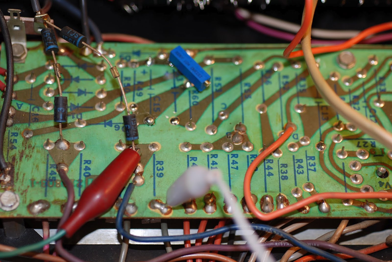
This pot is intended to replace R49 on the Ampeg schematic which is a 75k fixed resistor that sets the bias level.
The first thing I did was set the pot to about the same value as the resistor I removed. Then I started looking around for a good place to locate the trimmer. Looking on the underside of the circuit board I found a good place for it. I removed the third terminal and then, carefully heating the solder joints, pushed the wires from the Bourns trimmer in alongside the existing component leads.
You can also access the back sides of R40, 45, 46, and 39 which are the four plate resistors.
You should measure these for their actual value rather than their nominal value.
After a good warmup, I switched on and measured the VOLTAGE across R39 which read 73mv. Dividing 73 by the value of R39 which was 4.6 ohms gave me a plate current of 15 ma more or less, not enough at a plate voltage of 535v.
Carefully adjusting the pot upward I ended up at a final setting of 123.7 mv, which divided by 4.6 gives 26.9 ma of plate current. Adding in 4 ma of Kentucky windage to allow for screen current we're still well within what's allowable in this amp, with a margin for some upward drift as the tubes age.
While you're doing all this bear in mind you're working in close proximity to a live amp with some serious voltages. In addition, dropping things inside this live amp....well, the prospects are ugly. I made sure and insulated my trimmer screwdriver, although a plastic one would be even better. It goes without saying, easy does it and watch what you're doing.
I am just getting into biasing my own amp. I have a V4B that has a bias trimmer installed like you have described here. I understand your methodology here and I am comfortable taking the measurements and making the adjustments.
ReplyDeleteHow did you come to 26.9 ma as the proper plate current for this amp? That's the link that I think I am missing in this process.
Thanks,
Scot-
Measure your plate voltage and then skip on over to the Ted Weber forums website and use their bias calculator. It's quicak and easy.
ReplyDeleteHey guys, I appreciate the sharing of info. I'm un-experienced in this field and 1+1= 3. I have an ole V4 that has a stuck pot. Though I have the tools I'm not so confident to be making perfect solder joints. Anything I can do to get it working again without having to perform heart surgery?
ReplyDelete