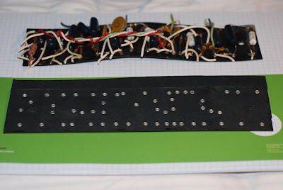
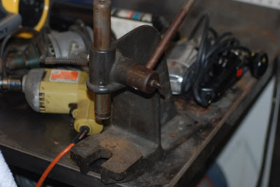
After taking another look at my arbour press which I got at a yard sale (I think) I realized that it had a reversible ram with a socket and a set screw. Installing my eyelet setting tool and clamping the arbor press to my workbench I used one of my old McDonnell Douglas bucking bars as an anvil. Of course what could be a better test than making another board? I took the mask I made as described and drilled the holes in a board for a 5F6A Bassman that is a long term project here. Then, I shaved the pushed up fiber material with a single edge razor blade and staked the eyelets, this time using the arbor press.
It does a fine job, clinches the eyelets just right and there are no loose ones either.
Perfect. I'm in business.
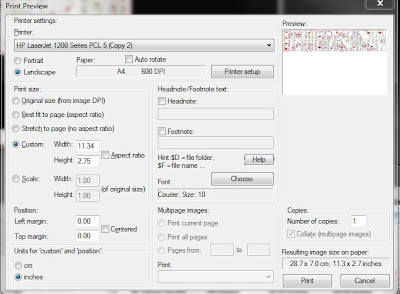
UPDATE: I think I may have figured the process of making drilling masks out without spending any more money than necessary. The problem seems to be that what you see on your screen may not print the same as you see it.
I've been working with the layouts in the Weber amp kits for practice but you could do this with any board as long as you have an image to start with that is relatively squarely done-if it's a photo that it would be a flat image where the object is not tilted or angled.
Then, you take and generate a second image using the Snipping tool in Windows 7 or Vista. You create an image of just the board, all by itself.
Then, using a freeware photo massaging utility called Irfanview that I found, you acquire the snipped image and select print.
The dialog box looks like the first image.
If you deselect aspect ratio you can re-size the image in two axes, it'll show you the printed image size, and you get a preview in the upper right.
So if you know the external dimensions of your board and you have a printer that can do legal size paper, you can take and generate a drilling mask very simply.
There ain't nothin' to this internet sheeyit, Jeeter.
I'm a great believer in convergence and synthesis, where several threads sort of organize themselves into something new and interesting. it is also said that when the student is ready, the teacher will appear.
So I've been tripping over the hulk of my Princeton Reverb a/k/a Ole Lumpy for some time now and looking at the doggy post CBS waxed circuit board with a certain sneer. At one and the same time I have an Ultralinear Twin Reverb that is getting reversed into something more normal circuit wise and I needed a smallish eyelet board for the bias and rectifier board which I obtained from Watts Tube Audio for about a ten spot.
So I asked who made a good eyelet board for my Princeton Reverb, and a fellow named Jeff Gehring said "You do, and I'll show you how."
There are two angles to this project, one of which is sourcing the materials and tooling, and the other is dimensioning. I'll deal with the first, well, first.
The material for Fender style eyelet boards is called black vulcanized fiber board. I bought some .062 thick board material from
Mojotone in 23-1/8 x 3 lengths. The eyelets are 1/8 x .156 and they're available from Mouser Electronics part number 534-45, and the eyelet staking tool is also available from Mouser for about ten bucks, part number 534-1715. You'll also need some 1/8 drill bits.
The board can be cut to the desired length and width with a pair of Wiss straight cut aviation shears-and buy the American stuff, get the best and support the home team y'all.
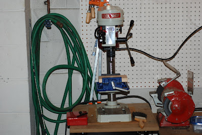
That's the basic stuff. It helps a lot of you have a drill press which doesn't have to be very fancy. I got mine for five bucks at an auction and Harbor Freight will sell you a small drill press for about fifty bucks which for this project will do fine. A drill vise is a necessity as is something to use as an anvil like the top of a bench vise.
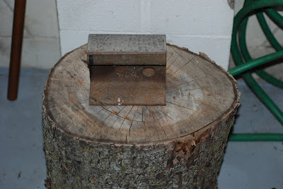
My anvil is a chunk of railroad iron sitting on top of a log that was part of the branch of one of the maples in the front yard that came down last year. I've also been thinking about using a small arbour press I have if I can adapt it to this purpose.
Drilling and deburring the 1/8 inch holes is no big problem, and using a razor blade to clean up the edges of the holes is simple enough. Place the eyelets through the board in the right direction, tape them in place and set them using the staking tool, a small hammer and an anvil.
The bigger problem is getting dimensions and/or a representation of what the board should look like in actual size. Here's how I worked around it.
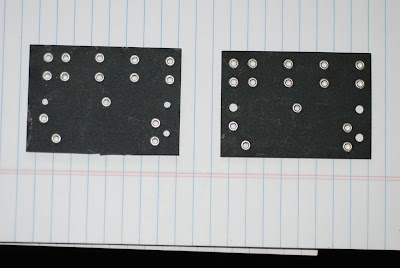
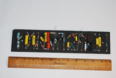
For the first try, a bias board, I scanned it on my flatbed scanner with a letter behind it for scale, checked it for size, cut it out and taped it to a blank board. I then drilled it, deburred it, installed the eyelets and staked them. The result is seen above. For tidying up the edges, you can clamp the finished product to a chunk of straight limber and use a sanding block and some number 40 sandpaper to shape it out.
I did the same thing with the old board for Ole Lumpy and stuffed it yesterday.
If you assume the typical brown face and later Fender eyelet board is 2-3/4 wide that becomes important. What I did was obtain a photo of a board and then use the snip tool function in Windows 7 to take what I needed from it. Then, using the scaling tool in Windows Photo Viewer, you can bring what you have up to 2-3/4 width on your monitor and then print it on legal size paper, deselecting the 'fit to frame' option.
A little rechecking and fine tuning and you should have a pretty good drill mask that will enable you to construct a board that will fit and work in your amp. Of course the best thing is to have an amp open for comparison or measurements.
Last and most important, don't use an ordinary lead pencil to mark on your new board. That creates resistors and current paths. Instead, a silver pencil or a china marker crayon is preferred.


